Time to read: 6 min
The different components of this manufacturing machine and how they work

Computer numerical control (CNC) machines, like mills and lathes, have become a fundamental part of modern manufacturing, and they don’t need much human intervention, saving companies both time and money. They’re designed to make parts automatically using a range of materials like metal, plastic, and wood, so understandably, they’re incredibly useful. Let’s have a look at the inner workings of a CNC machine to better understand how exactly it works.
CNC Machine Components
CNC machines are made up of several complex components that all work together to make the machines function and quickly produce precise parts. You’ll find descriptions of each of them below.
Input Device
This is basically the way CNC programs are loaded into the machine. It could be as simple as a keyboard (to directly input G-code commands), a USB flash drive with the completed program already on it, or some form of wireless communication if you want to download the program from another computer.
Machine Control Unit (MCU)
This component refers to a collection of software and hardware that’s responsible for reading the G-code that comes in from the input device and translating it into actual instructions for the machine and all its tools to follow. Safe to say, the MCU is one of the most important components of the entire machine as it forces the servo motors to get to work along the various axes. It also makes sure that the tools are where they should be after the movement is completed and controls the tool changers and the activation of the coolant. This is what a typical control unit looks like:The different components of this manufacturing machine and how they work
Driving System
This refers to the collective motors that move the tools around. In a traditional CNC mill, the bed moves horizontally (along the x- and y-axes), and the tool goes up and down (z-axis). In a CNC lathe, the tool moves in the same direction as the rotating workpiece, and goes to the outer edge as it rotates instead of across the part. Servo motors, ball screws, and linear guides keep everything moving and in sync.
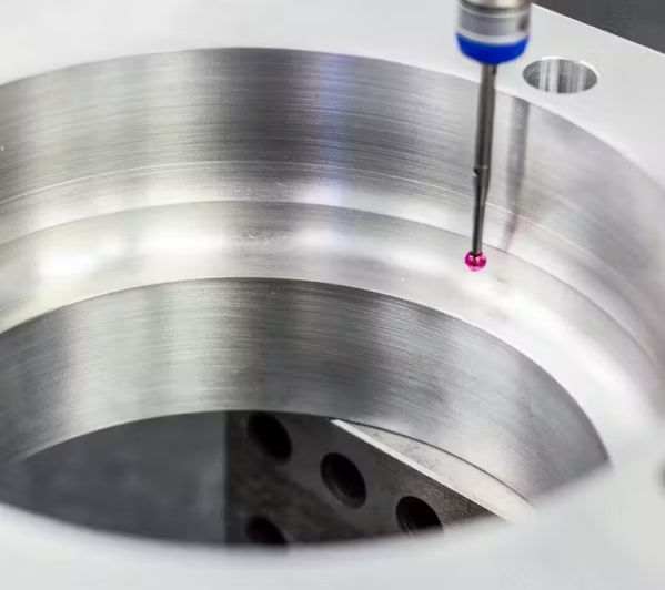
Feedback System
This system works kind of like a backup. The driving system is incredibly accurate, but this closed-loop control system is a way to verify whether parts move to where they should. If they’re slightly off, it will adjust them with encoders, sensors that measure each component’s position. Probes also play a role; they measure the actual workpiece and ensure everything is going as planned. If any adjustments need to be made, the machine will simply make them automatically. This is what a probing tool usually looks like:
Driving System
This refers to the collective motors that move the tools around. In a traditional CNC mill, the bed moves horizontally (along the x- and y-axes), and the tool goes up and down (z-axis). In a CNC lathe, the tool moves in the same direction as the rotating workpiece, and goes to the outer edge as it rotates instead of across the part. Servo motors, ball screws, and linear guides keep everything moving and in sync.
Feedback System
This system works kind of like a backup. The driving system is incredibly accurate, but this closed-loop control system is a way to verify whether parts move to where they should. If they’re slightly off, it will adjust them with encoders, sensors that measure each component’s position. Probes also play a role; they measure the actual workpiece and ensure everything is going as planned. If any adjustments need to be made, the machine will simply make them automatically. This is what a probing tool usually looks like:
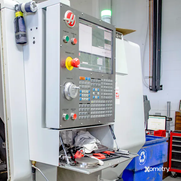
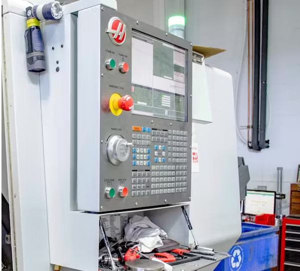
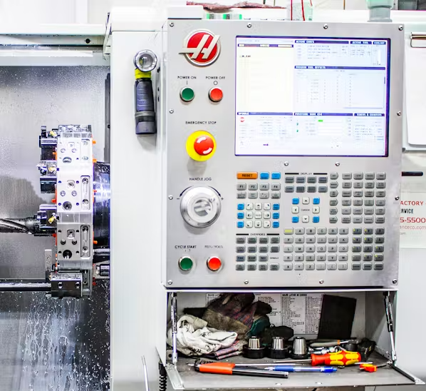
Display Unit
This one’s pretty self-explanatory. It’s basically a screen that shows all the important information on it while the work is being done (like the machine’s settings, G-code, and current operating status). Some machines have huge high-definition screens with a plethora of information on them, but others can be quite small, with only the bare necessities being shown. The following image is an example of one such unit:
Bed
The bed is where the raw material is placed, and it contains a bunch of holes or t-slots for jigs that hold the object in place. A lot of traditional machine beds only move horizontally (x- and y- axes), but some of the more advanced 5-axis machines have beds that can also rotate along the same axes. When it comes to a CNC lathe, though, the tool turret and tailstock are attached to the bed, and the raw material is held in place by the chuck. Here’s an example of a part mounted to a CNC mill bed:
Headstock
The headstock is found on the left side of a CNC lathe. It houses the main drive, bearings, and gears that spin the chuck. It’s enclosed, but it can be accessed by removing some inspection panels.
Tailstock
This is the part of a lathe that supports one end of a long, cylindrical workpiece, while the chuck holds and spins the other end. It’s an important part of the machine that stops the material from bending during the process. It can move up and down the z-axis to accommodate different material lengths and comes in especially handy for things like shafts or screws.
Tailstock Quill
The quill is inside the tailstock and is a cone-shaped structure that’s aligned with the spindle and chuck. It rotates freely and keeps the material centered. For long parts, a blind hole is usually drilled into the end of the piece so that the quill can fit inside it for some support. After the tailstock is in place—close to the workpiece—the quill is pushed in by pneumatic or hydraulic pressure.
Footswitch or Pedal
These pedals are typically only found on lathes because they activate and deactivate the chuck and tailstock quill. They basically allow the operator to load blanks into the machine and unload completed parts. CNC mills don’t usually need pedals or footswitches because the parts are already supported on the bed, and the operators don’t need to have both hands free when loading and unloading.
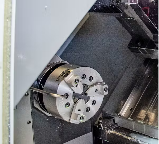
Chuck
Something we’ve mentioned a few times already, the chuck is specific to lathes and is used to grip the workpiece while it’s being worked on. The spindle keeps it rotating at a rather high speed. Generally speaking, a chuck will have three or four pneumatically or hydraulically actuated grips. Chucks that have three jaws are self-centering, which means that all the grips move evenly together. Those with four jaws are typically adjustable, with each grip able to move on its own. They’ll also have more features than chucks with fewer jaws. For instance, they’re more precise, allowing for eccentric or off-center cutting, and they’re better at handling inconsistencies with the material. This is what a traditional three-jaw chuck looks like: